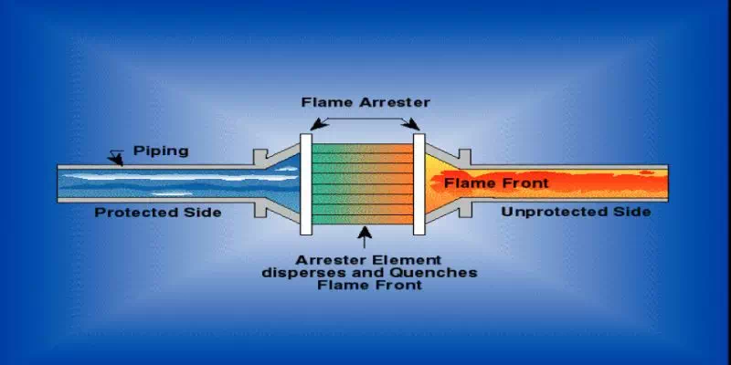
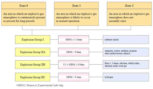
Gap of Flame Element MESG of Chemical MESG: Maximum Experimental Safe Gap *For example, MESG of propane is 0.965mm.
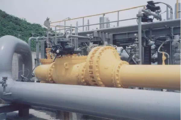
Example of Detonation Flame Arrester
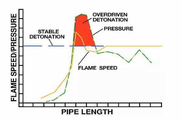
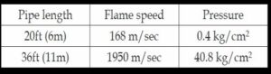
Effect of run-up length on pressure and flame
Basic information for ordering flame arrester
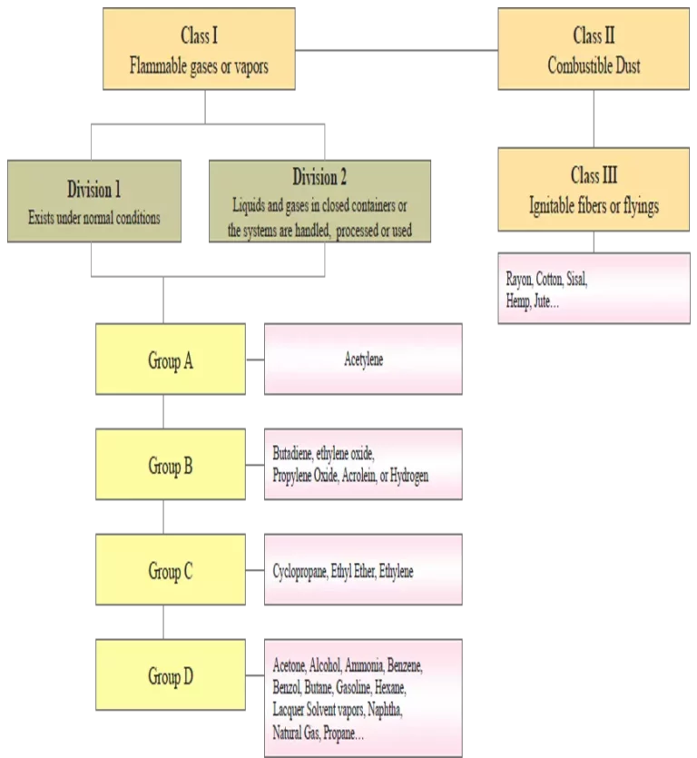
Kind of mixture of gases or vapors, and their concentrations
Type (End-of-line/In-line, Deflagration/Detonation)
Maximum operating pressure
Normal operating pressure (if possible)
Operating temperature ranges
Normal operating temperature (if possible)
Size and connection (ex, 4” – JIS 10K Raised Face Flange)
Material of body and flame element
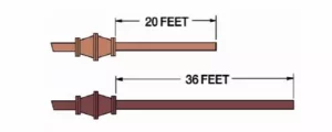
In case of in-line type, configuration of pipe system and dimensional information (Deflagration Flame arrester should be installed at nearest position from potential ignition source. We recommend it must be installed within 20 times of pipe diameters of the open end of the vent pipe or the potential ignition source.)
Acceptable pressure drop at flame arrester
Set pressure, vacuum (for flame arrester with integrated pressure/vacuum relief valve)
Effect of pipe length on pressure and flame speed
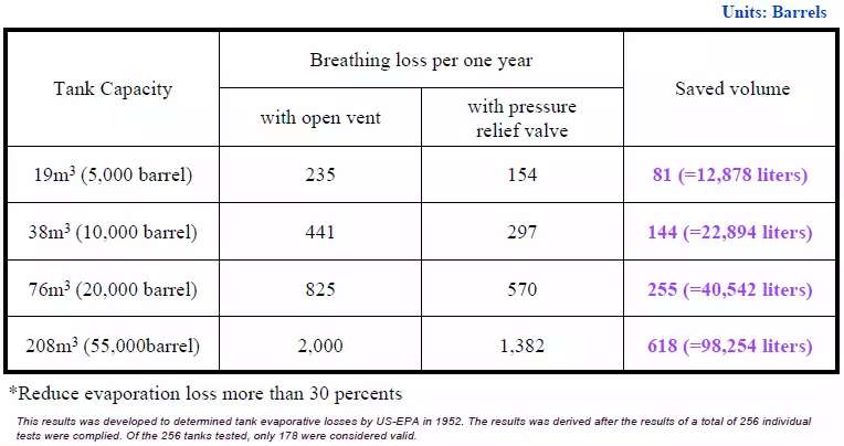
Breathing Loss Comparison Table
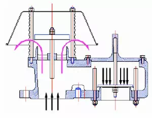
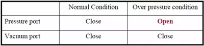
Pressure Relief
Basic Requirements of Relief Valve
Anti-corrosion to the handling chemical
Maximum venting capacity of valve – Normal venting requirement – Thermal venting capacity – Other venting requirements due to chemical reactions, internal or external heat transfer device, etc. ※ These requirement are specified in API 2000 Standard.
Sealing
Basic information for ordering pressure/vacuum relief valve
Kind of chemical, their concentrations and physical status
Type (Pressure relief, vacuum relief, pressure and vacuum relief)
Storage tank capacity
Design pressure and/or design vacuum of storage tank
Normal operating pressure/vacuum of storage tank
Set pressure and/or set vacuum of relief valve
Emergency Venting Device
Emergency Venting for Tank subject to Fire Exposure
Secondary Safety Device for Emergency
Large sized and High Capacity
Access for Maintenance (Large sized model)
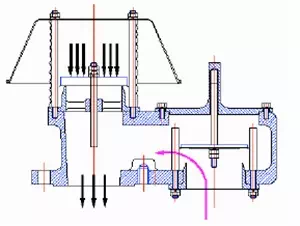
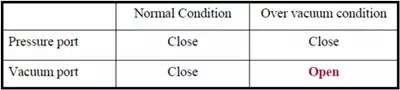
Vacuum Relief
Causes of Overpressure or Vacuum
Liquid Movement into or out of a Tank
Weather Change
Fire Exposure
Utility or System Failure (Internal or External Heat Transfer Device, Venting device etc.,)
Other Circumstances
Maximum filling rate
Maximum discharging rate
Insulation thickness of storage tank
Size and connection (ex, 4” – JIS 10K Raised Face Flange)
Materials of body, seat, pallet, and diaphragm
Other information and specification to be considered